


How much open spring pressure did you have when you found the whip?Originally Posted by saltracer

I'm concerned about the wear characteristics of a chrome moly shaft. Maybe it could be hard chromed or nitrided?

 Senior Member

Titanium doesn't have very good wear properties with dissimilar metals, unless its plasma coated, like a valve stem or connecting rod face, chrome moly would be more than adequate. Since roller cams do require considerably higher spring pressures, both closed and open, it would be recommended that upgrading to a better rocker stand and rocker shaft would be something to be considered mandatory if using one.
Last edited by CNC-Dude; 02-08-2012 at 11:30 PM.
There's no such thing as too much cam....only not enough engine!
How much open spring pressure did you have when you found the whip?
I'm concerned about the wear characteristics of a chrome moly shaft. Maybe it could be hard chromed or nitrided?
Member
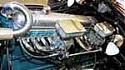
The stock stands are prone to cracking at the base, see attached picture.
No fancy laser, all done on a vertical mill. I now have washers under all the bolts, when I did the test fitting I didn't have enough of the longer bolts.
I'm actually not surprised the stand breaks under the stresses of heavier valve springs. The '46 320 has 50 lbs seat pressure, and the '49 has 75 lbs. Any performance build should start from 100+ lbs
I'm wondering why Buick made the stands out of aluminum, of all things?
Senior Member
Funny ....
My 263 is in parts on shelves, and I had a look at the stands .
One is 3/4 cracked ....
Is it safe to weld it, or as I have acces to a mill, should I build new ones like ebbsspeed did ?
Member
nali, I would make new ones, especially if you have access to a mill. Then you never have to worry about them again. Mine are made of steel, but you could also mill them out of aluminum, and sculpt them somewhat to take some weight off. I wasn't concerned with weight, just wanted something solid. FYI, in post number 2 of this thread, there is a drawing that I posted way back in 2009 with the dimensions for the stands. One thing that the drawing doesn't show is the additional 45 degree cuts on two of the edges to give a little additional clearance by the valve springs. You can see those cuts on some of the other pictures I posted in this thread. Another change was that the drawing shows the cut through the center of the rocker shaft hole going all the way through. The machinist that made mine decided that it would be better to leave a short section of the metal intact in order to create a "pivot" point performs a couple of functions. First of all, it keeps you from having to keep track of what would be the upper and lower sections of each stand. Second, it allows you to torque the bolt on the pushrod side to full torque without worrying about crushing the rocker shaft, since the clamping force of the bolt is transferred through the pivot to the base of the stand..
Last edited by ebbsspeed; 02-09-2012 at 03:17 PM.
Senior Member
Thanks a lot ebbsspeed . I didn t see or forget about your drawing ..
So much information on this forum ....
Are the dimension right, since you didn t seem to be sure on the #2 post ?
This will avoid me to take measurements
I can have them made or whatever I want. Alu, SS, steel, cooper, wood
This could be a nice learning lesson, the stands are really simple things.
So I like the alu idea. Even square like yourse. Weight is a detail .... Maybe we can loose 1 lbs sculpting them ...
I just have to think more about the "pivot" section. I don t really understand this, english is not my native language. But I think I got the idea .
Member
nali, all the dimensions are close, except you will notice that, if you look at the drawing and then the actual stand that I had made, the rocker shaft bore is offset towards the "clamp" side of the stand. It is not in the center. I gave the machinist that made mine one of the original stands, and he took measurements from it.
Post pictures of your finished product!
Senior Member
Yes I have a stock cam I can send you........but let me check to make sure the lifter lobes are in the center of the lifter bores......something in the back of my mind tells me that the stock lifters were flat on the botom and offset to rotate the lifter ??? damn sure want the rollers to be in center. Good Luck I'll get back to you
Senior Member
Stock lifters have a slight convex radius on the bottom and the cam lobes are tapered so one end is slightly larger than the other. This is what causes the lifters to rotate. Not sure about the bores being offset, but that is certainly possible too.
Ray
 Posting Permissions
Bookmarks