"Buick Trademark(s) used with the written permission of General Motors"

| BOLT TORQUE SPECIFICATIONS | ||
| LOCATION | THREAD SIZE | TORQUE |
| Spark Plug | 14MM | 22-28 |
| Crankcase Drain | 28MM | 30-35 |
| Lower Crankcase | 5/16-18 | 6-15 |
| Flywheel Housing to Upper Crankcase | 7/16-14 | 55-60 |
| Timing Gear Cover | 3/8-16 | 15-20 |
| Valve Push Rod Cover | 5/16-18 | 4-5 |
| Valve Rocker Arm Cover | 5/16-24 | 4-5 |
| Water Pump Mounting | 3/8-16 | 25-30 |
| Manifold Stud | 3/8-24 | 25-30 |
| Cylinder Head | 7/16-14 | 65-70 |
| Con. Rod Bolt - Series 40-50 | 3/8-24 | 40-45 |
| Con. Rod Bolt - Series 70 | 7/16-24 | 60-65 |
| Piston Pin Clamp | 5/16-24 | 25-30 |
| Crankshaft Bearing Clamp | 1/2-13 | 90-100 |
| Balancer Retaining | 3/4-16 | 100-110 |
| Flywheel to Crankshaft, Synchromesh | 3/8-24 | 35-40 |
| Flywheel to Crankshaft, Dynaflow | 7/16-24 | 50-55 |
| Rocker Arm Shaft Bracket | 3/8-16 | 30-35 |
| Rocker Arm Shaft Bracket Stud | 3/8-24 | 30-35 |
| Generator to Bracket Bolt | 3/8-24 | 25-30 |
| Generator Mounting Bracket to Crankcase | 3/8-16 | 30-35 |
| Front Engine Mounting Bracket to Frame Bolt | 3/8-24 | 30-35 |
| Front Engine Mount Stud | 3/8-24 | 30-35 |
| Transmission Mounting Pad to Rear Bearing Retainer | 3/8-16 | 30-35 |
| Transmission Mounting Pad to Transmission Support Bolt | 3/8-24 | 30-35 |
| Transmission Support to Fame Cross Member Bolt | 3/8-24 | 20-25 |
| Thrust Pad to Transmission Support and Thrust Plate | 3/8-24 | 30-35 |
| GENERAL SPECIFICATIONS | ||
| General Information
Items |
Series 40-50 | Series 70 |
| Type | <------------Valve in Head-----------> | |
| Cylinders and Arrangement | <---------------8 in Line-------------> | |
| Bore and Stroke | 3 3/16" X 4 1/8” | 3 7/16"X 4 5/16” |
| Piston Displacement | 263.3 | 320.2 |
| Compression Ratio | ||
| Synchromesh - Series 40 Only | 6.6 to 1 | --- |
| Synchromesh - Series 50 Only | 6.9 to 1 | --- |
| Dynaflow - All Series | 7.2 to 1 | 7.5-1 |
| Compression Pressure @ Cranking Speed (psi) | ||
| Synchromesh - Series 40 Only | 114 | --- |
| Synchromesh - Series 50 Only | 118 | --- |
| Dynaflow - All Series | <-----------------120----------------> | |
| Firing Order | <----------1-6-2-5-8-3-7-4----------> | |
| Taxable Horsepower | 32.51 | 37.81 |
| Max B.H.P. @ RPM. | ||
| Synchromesh - Series 40 Only | 120 @ 3600 | --- |
| Synchromesh - Series 50 Only | 124 @ 3600 | --- |
| Dynaflow - All Series | 128 @ 3600 | 168 @3800 |
| Engine Weight, Less Clutch and Mountings (lbs.) | 746 | 749 |
| 833 | ||
| Number of Mounting and Material | <----------3 Synthetic Rubber---------> | |
| Cylinder Crankcase and Cylinder Head | ||
| General Information
Items |
Series 40-50 | Series 70 |
| Cylinder Crankcase Type | <---Black Cast Integral with Crankcase---> | |
| Cylinder Head Type and Material | <----------One Piece, Cast Iron---------> | |
| Combustion Chamber | <---------------Cast in Head------------> | |
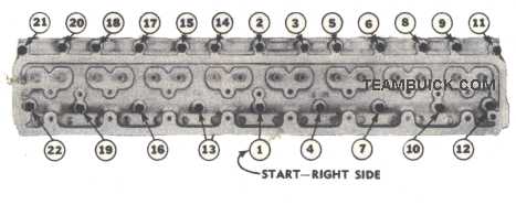
| Head Bolts, Number and Diameter | <----------------22, 7/16″--------------> | |
| Crankshaft Bearings, Flywheel Balancer | ||
| Crankshaft Weight (lbs.) | 90 | 116 |
| Number of Crankshaft Bearings | 5 | 5 |
| Bearing Which Takes Thrust | <-----------------Center----------------> | |
| Crankshaft Bearing Type | <-------------Replaceable Liners----------> | |
| Crankshaft Bearing Material | <---------Steel Backed Durex 100A-------> | |
| Provision for Bearing Adjustment | <-----------------None------------------> | |
| Bearing Cap Bolts, No. and Diam. | ||
| Rear Bearings | Two 1/2” | Four 1/2” |
| Other Bearings | Two 1/2” | Two 1/2” |
| Flywheel | ||
| Material and Weight, Synchromesh | C.I.-36.56 | --- |
| Material and Weight, Dynaflow | Steel - 9.23 | Steel - 12.21 |
| Number of Teeth on Ring | 146 | 156 |
| Crankshaft Balancer Type | <--Laminated Steel Flywheel on Steel Leaf Springs--> | |
| Balancer Location | <---------Front End of Crankshaft---------> | |
| Connecting Rods, Pistons and Rings | ||
| Connecting Rod Bearing Type | <---------Steel Backed Durex 100-A--------> | |
| Connecting Rod Bearing Material | <--------------Replaceable Liners------------> | |
| Provision for Bearing Adjustment | <------------------None-------------------> | |
| Number and Diam. of Cap Bolts | Two 3/8” | Two 3/8” |
| How are Rods and Pistons Removed | <-----------From Top of Cylinder-----------> | |
| Piston Type | <----------------Full Skirt----------------> | |
| Piston Material and Surface Treatment | <--------Aluminum Alloy - Anodized-------> | |
| Compression Rings Per Piston | 2 | 2 |
| Type | <--------------Inside Bevel---------------> | |
| Oil Rings Per Piston | 2 | 2 |
| Type, Upper | <-------Channeled - Oil Return Slot-------> | |
| Type, Lower | <----------------Flex-Fit-----------------> | |
| Location of All Piston Rings | <------------Above Piston Pin------------> | |
| Camshaft and Valve Mechanism | ||
| Camshaft Drive | <-------------Link Belt Chain------------> | |
| Number of Camshaft Bearings | 5 | 5 |
| Camshaft Bearing Material | <----------Steel Backed Babbitt---------> | |
| Camshaft Thrust Control | <-----------Plate at Front End-----------> | |
| Camshaft Sprocket | ||
| Material and Width | <------------Cast Iron, 13/16″-----------> | |
| No. of Teeth | 38 | 38 |
| Crankshaft Sprocket | ||
| Material and Width | <--------------Steel, 13/16″-------------> | |
| No. of Teeth | 19 | 19 |
| Timing Chain Width | 13/16” | 13/16” |
| Valve Lifter Type | ||
| Series 40, Synchromesh only | Plain Sleeve | --- |
| Series 50, All Dynaflow | <---------------Hydraulic----------------> | |
| Valve Type | ||
| Inlet | <--------------Streamlined---------------> | |
| Exhaust | <---------------Mushroom----------------> | |
| Valve Seat Angle, Inlet and Exhaust | <--------------45 Degrees---------------> | |
| Valve Spring Type | <--------------Dual Helical---------------> | |
| Valve Guide Type and Material | <---------Removable, Cast Iron-----------> | |
| Engine Oiling System | ||
| Oiling System Type | <--------------Forced Feed---------------> | |
| Oil Supplied to Bearing Surfaces - | ||
| Crankshaft Bearings | <----------------Pressure-----------------> | |
| Connecting Rod Bearings | <----------------Pressure-----------------> | |
| Pistons and Pines | <-----------------Spray-------------------> | |
| Camshaft Bearings | <----------------Pressure-----------------> | |
| Timing Chain and Sprockets | <----------Metered Jet and Spray---------> | |
| Rocker Arms and Valves | <--------------Low Pressure--------------> | |
| Valve Lifters | <--------------Low Pressure--------------> | |
| Location of Oil Filter | <--------In Valve Rocker Arm Cover-------> | |
| Location of Oil Drain | <----------Plug in Lower Crankcase--------> | |
| Oil Reservoir Capacity - Quarts (add 1 1/2 qts for dry oil filter | ||
| Dry Engine | 6 | 8 |
| Refill | 5 1/2 | 7 |
| Oil Level Gauge | <---------Rod in R. Side of Crankcase--------> | |
| Oil Level Pressure Gauge Make | <-------------------A/C------------------> | |
| Normal Oil Pressure | <------------35 lbs. at 35 mph.-----------> | |
| Oil Pump Type | <---------------Helical Gear--------------> | |
| Oil Pump Location | <------Suspended in Lower Crankcase-----> | |
| Oil Screen Location | <-------On Float Attached to Pump-------> | |
| Oil Pressure Regulator Type | <-----Non-Adjustable Spring and Valve-----> | |
| Engine Cooling System | ||
| Cooling System Type | <----------------Pressure-----------------> | |
| Water Temperature Control | <-------Thermostat and Fixed Bypass------> | |
| Cooling System Capacity - Quarts (Add 1 1/2 qts. for Dynaflow) | ||
| Less Heater | 12 | 18 |
| With Heater | 13 1/2 | 19 1/2 |
| Location of Drains | <-Cocks in Rad. and in R.H. Side of Crankcase-> | |
| Water Pump Type | <---------------Centrifugal----------------> | |
| Water Pump Location | <---------Front End of Crankcase----------> | |
| Water Pump and Fan Drive (With Generator) | <----------Single Vee Belt-------------> | |
| Water Pump to Crankshaft Speed Ratio | <-----------------0.9 to 1----------------> | |
| Water Pump Bearing Type | <---------Sealed Double Row Ball----------> | |
| Water Pump Seal Type | <---------Spring Loaded, Packless---------> | |
| Fan Diameter | <------------------18"--------------------> | |
| Number of Blades | 4 | 5 |
| Radiator Make | <------------------Harrison---------------> | |
| Core Type | <---------------Vee Cellular---------------> | |
| Core Material | <------------------Copper----------------> | |
| Core Frontal Area (sq. in.) | ||
| Synchromesh | 415 | --- |
| Dynaflow | 484 | 484 |
| Core Thickness | 2” | 3” |
| Radiator Pressure Control | <-------------Valve in Filler Cap-----------> | |
| Radiator Pressure | <------------------7 lbs.-----------------> | |
| Radiator Thermostat - Make | <-----------------Harrison----------------> | |
| Thermostat Location | <-------In Housing Above Water Pump-----> | |
| ENGINE DIMENSIONS AND FITS NOTE:Dimensions and limits for fir of parts apply to new parts only. Where limits are given, "T" means tight and "L" means loose. *A11 Measurements in Inches Unless Otherwise Specified. |
Crankshaft and Connecting Rod Bearings |
||
Series 40-50 |
Series 70 |
|
Crankshaft Bearing - Nominal Diam. X Length |
||
-Front |
2 9/16" x 1 17/64” |
2 9/16" x 1 9/32” |
-Front Center |
2 9/16" x 1 1/32” |
2 5/8" x 31/32” |
-Center |
2 9/16" x 1 35/64” |
2 11/16" x 1 15/32” |
-Rear Center |
2 9/16" x 1 1/32” |
2 13/16" x 2 15/32” |
-Rear |
2 9/16" x 1 25/32” |
2 13/16" x 2 15/32” |
Crankshaft Journal Diameter |
||
-Front |
2.5625" - 2.5632” |
2.5605" - 2.5615” |
-Front Center |
2.5625" - 2.5632” |
2.6235" - 2.6245” |
-Center |
2.5625" - 2.5632” |
2.6855" - 2.6865” |
Center Rear |
2.5625" - 2.5632” |
2.7485" - 2.7495” |
-Rear |
2.5625" - 2.5632” |
2.8105" - 2.8115” |
Fillet Radius |
.125" |
|
Thrust Width |
1.5490" |
|
Crankshaft Bearing to Journal Clearance |
.0006" - .0018” |
.0006" - .0020” |
Crankshaft End Play at Center Bearing |
.004" - .008” |
|
Fit to Main Drive Gear Pilot Bearing in Crankshaft |
.004"T to .0012"L |
--- |
Connecting Rod Bearing Nominal Diam. x Length |
2 1/8" x 1.030” |
2 1/4" x 1.306” |
Crank pin Journal Diameter |
2.125" - 2.126” |
2.248" - 2.249” |
Crank pin Journal to Bearing Clearance |
.0005" - .0016” |
|
End Clearance to Connecting Rod on Crank pin |
.005" - .010” |
|
Connecting Rod Length, Center to Center |
7 3/8” |
8 1/4” |
Cylinders, Pistons, Pins and Rings |
||
Cylinder Bores, Standard Size |
3.186" - 3.189” |
3.436" - 3.439” |
Piston Length, Overall |
3 49/64” |
4 9/16” |
Piston Diameter, Top of Skirt, at 90° to Piston Pin - |
||
-Standard |
3.1860" - 3.1872” |
3.4358" - 3.4370” |
-.005" Oversize |
3.1916" - 3.1922” |
3.4414" - 3.4420” |
-.010" Oversize |
3.1966" - 3.1972” |
3.4464" - 3.4470” |
-.020 Oversize |
3.2066" - 3.2072” |
3.4564" - 3.4570” |
-.30" Oversize |
3.2166" - 3. 2172” |
3.4664" - 3.4670” |
Piston Clearance in Cylinder Bore at Top of Skirt |
.0012" - .0018” |
.0014" - .0020” |
Piston Fit @70º F., using Feeler Gauges, Allowing Piston to Drop on its Own Weight |
.0015" GO - .002" NO GO |
|
Piston Pin Length |
2 11/16” |
3 1/16” |
Piston Pin Diameter |
.8124" - .8129” |
.8744" - .8749” |
Piston Pin Fit in Piston at 70º F. |
Finger Push Fit (.0003" - .0005") |
|
Width of Compression Rings |
3/32” |
3/32” |
Width of Channeled Oil Rings |
3/16” |
3/16” |
Width of Flex-Fit Oil Rings |
.186" - .187” |
|
Width of Gap, Ring in Bore - |
||
-Compression and Upper Oil Ring |
.010" - .020” |
|
Flex-Fit Oil Ring |
No Checking or Fitting Required |
|
Side Clearance of Rings in Piston Grove - |
||
-Compression Ring |
.0015" - .0035” |
|
-Upper Oil Ring |
.0015" - .003” |
|
-Flex-Fit Ring |
.001" - .003” |
|
Camshaft and Valve Mechanism |
||
Camshaft End Play |
.004" - .009” |
|
Camshaft Bearings - Diam. x Length - |
||
-No. 1 |
2 5/32" x 1 1/8” |
|
-No. 2 |
2 1/8" x 3/4” |
2 1/8" x 1 1/8” |
-No. 3 |
2 3/32" x 1 1/8” |
|
-No. 4 |
2 1/16" x 3/4” |
2 1/16" x 15/16” |
-No. 5 |
1 3/4" x 31/32” |
|
Camshaft Clearance in Bearings |
.0015" - .004” |
|
Valve Lifter Diameter |
.9975" - .9985” |
|
Valve Lifter Clearance in Crankcase |
.0005" - .0025” |
|
Rocker Arm Shaft O. D.> |
13/16” |
13/16” |
Rocker Arm Clearance on Shaft |
.002" - .004” |
|
Valve Head Diameter - |
||
-Inlet |
1 17/32” |
1 25/32” |
-Exhaust |
1 11/32” |
1 7/16” |
Valve Seat Angle - Inlet and Exhaust |
45º |
|
Rocker Arm Ratio - |
1.45 |
|
Valve Lift - |
||
-Inlet |
.348” |
.347” |
-Exhaust |
.342” |
.348” |
Valve Stem Diameter - |
||
-Inlet |
.3715" - .3719” |
|
-Exhaust |
.3711" - .3719” |
|
Valve Stem Clearance in Guide - |
||
-Inlet |
.0015" - .0035” |
|
-Exhaust |
.0021" - .0039” |
|
Valve Guide Extension from Top of Cyl. Head |
1 5/32” |
1 5/32” |
Inner Valve Spring, Used with Adjustable Valve Lash - |
||
-Valve Open (lbs. @ length) |
48 - 54 @1 5/16” |
--- |
-Valve Closed (lbs. @ length) |
17.5 - 22.5 @ 1 21/32” |
--- |
Outer Valve Spring, Used with Adjustable Valve Lash - |
||
-Valve Open (lbs. @ length) |
74 - 80 @1 19/32” |
--- |
-Valve Closed (lbs. @ length) |
29.5 - 34.5 @ 1 15/16” |
--- |
Inner Valve Spring, Used with Hydraulic Lifters - |
||
-Valve Open (lbs. @ length) |
49 -55 @1 5/16” |
|
-Valve Closed (lbs. @ length) |
22 - 26 @ 1 21/32” |
|
Outer Valve Spring, Hydraulic Lifters - |
||
-Valve Open (lbs. @ length) |
96 - 104 @ 1 19/32” |
|
-Valve Closed (lbs. @ length) |
49 - 55 @ 1 15/16” |
|
Valve Lash - Series 40 Synchromesh NOTE: Does not apply to engines equipped with hydraulic valve lifters. |
||
Valve Lash at Road Operating Temp., Inlet and Exhaust - |
.015” |
--- |
Valve Lash using Shop Procedure |
.017”Go-.018”No Go |
--- |
Engine Oil System |
||
Pump Shaft to Bearing Clearance |
.0005" - .0020” |
|
Pump Idler Gear Bearing Clearance |
.001 - .0025” |
|
Pump Drive Gear Backlash |
.003" - .005” |
|
Pump Drive and Idler Gears Backlash |
.003 - .006” |
|
Pump Drive and Idler Gears End Clearance |
.003 - .006 |
|
Oil Pressure Valve Clearance in Body |
.003" - .006” |
|
Engine Cooling System |
||
Fan Belt Adjustment |
5/16” |
|
Fit of Bearing in Water Pump Body |
.0006T to .0009"L |
|
Pump Bearing Shaft Diameter |
5/8” |
5/8” |
Fan Hub Fit on Bearing Shaft |
.001"T - .0025"L |
|
Fan Hub Position on Bearing Shaft |
13/64" from end |
|
Radiator Hose Inside Diam. and Type |
1 9/16" Elbow |
|
Bypass Hose Inside Diameter |
3/4” |
|
Standard (151° ) Radiator Thermostat Calibration, @Atm. Press. - |
||
-Start to Leave Seat |
148° to 155° |
|
-Fully Open |
Not over 176° |
|
Standard (182° ) Radiator Thermostat Calibration, @Atm. Press. - |
||
-Start to Leave Seat |
178° to 185° |
|
-Fully Open |
Not over 211° |
|
Blue Print Specifications |
|||
248 |
263 |
320 |
|
Bore |
3 3/32”” |
3 3/16”” |
3 7/16”” |
Stroke |
4 1/8” |
4 1/8” |
4 5/16” |
Cylinder Head Volume |
98cc |
116cc |
|
Piston Dome Volume |
9.5cc |
14cc |
|
Deck Clearance |
.0012” - .0018” |
.0014” - .0020” |
|
Deck Height |
|||
Rod Length |
7.625" |
7.375" |
8.250" |
Rod/Stroke Ratio |
1.848" |
1.787" |
1.913" |
Bore/Stroke Ratio |
0.750" |
.773" |
.798" |
| 263 Bore pitch: cylinders #1-2, 3-4, 5-6, & 7-8 are 3.725" apart, cylinders #2-3, & 6-7 are 3.750" apart and cylinders #4-5 are 4.185" apart 320 Bore pitch: cylinders #1-2, 3-4, 5-6, & 7-8 are 4.075" apart, cylinders #2-3 & 6-7 are 4.290" apart, and cylinders #4-5 are 4.545" apart. |
|||