"Buick Trademark(s) used with the written permission of General Motors"

Engines are equipped with either Stromberg or Carter Carburetors in production. The equipment on any engine is considered as "standard". It is not intended that these units be interchanged to provide "optional" equipment.
Series 40 engines are equipped as "standard" with one dual carburetor. This series is also available "optionally" equipped with compound carburetion. This means that two dual carburetors are used on one dual manifold.
Series 50-60-70-90 engines are equipped as "standard" with compound carburetion. Single dual equipment is not available on these series.
Engines equipped with compound carburetion use two dual carburetors mounted on one dual manifold. See Fig. 6-58.
The outside branch of manifold is connected to outside barrel of both carburetors and feeds cylinders Nos. 1, 2, 7 and 8. See Figs. 6-50, 6-51.
The inside branch of manifold is connected to inside barrel of both carburetors and feeds cylinders Nos. 3, 4, 5 and 6.
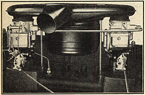
This arrangement of carburetors and manifolds makes it possible for either front or rear carburetor to feed to all eight cylinders.
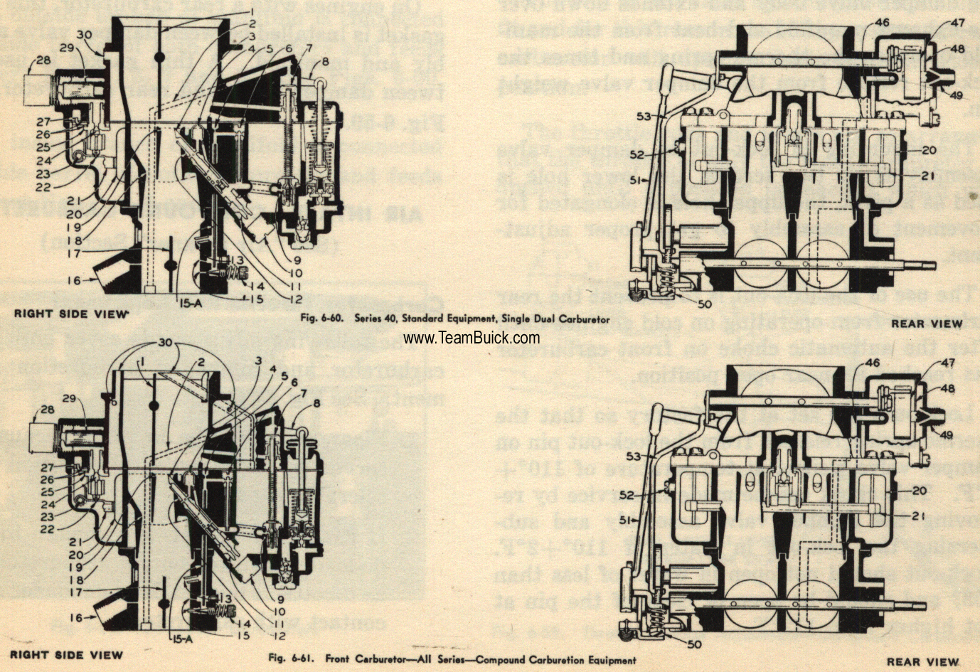
The front carburetor is complete and includes a float system, main metering system, accelerating pump, power by-pass system, idling system, starter switch, and automatic choke. See Figs. 6-66, 6-73.
The rear carburetor contains only a float system, idling system, and main metering system.
When engine is idling and up to approximately 22 M.P.H. part throttle, the idling systems of both carburetors are in operation.
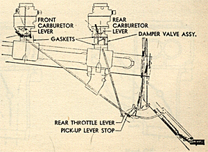
A damper valve assembly is used between rear carburetor and intake manifold. See Fig. 6-59. Except under conditions described below, this valve is held in closed position by an offset weight and serves to govern the operation of the rear carburetor.
The flies in this valve assembly are not a tight fit and for this reason the idling system of rear carburetor will operate with valve in closed position.
The throttle rods and levers are so arranged that the throttle of only the front carburetor is opened until a position is reached which will
give approximately 75 M.P.H. on part throttle. Up to this point of opening only the front carburetor operates except for idle system of rear carburetors as previously described.
Additional movement of accelerator pedal will start to open throttle of rear carburetor. Opening of rear carburetor throttle allows air flow through rear carburetor to open damper valve and bring rear carburetor into operation.
When throttles of both carburetors are fully opened, the front and rear carburetors feed equally.
If accelerator pedal is fully depressed at low speed, only the front carburetor operates until manifold vacuum is sufficient to open flies of damper valve assembly. This will begin to occur at approximately 15 miles per hour.
Damper Valve Lock-Out
A new thermostat lockout has been designed and is attached as an assembly to the rear carburetor damper valve, which controls the cut-in period of damper valve when engine is cold.
The thermostat and bracket is mounted to the damper valve body and extends down over the exhaust manifold and heat from the manifold operates the thermo spring and times the lock-out release from the damper valve weight pin.
The mounting of lock-out to damper valve assembly is by two screws, the lower hole is used as a pivot, the upper hole is elongated for movement of assembly to get proper adjustment.
The use of the lock-out is to prevent the rear carburetor from operating on cold engines until after the automatic choke on front carburetor has reached its near open position.
Lock-outs are set at the factory so that the thermo spring releases from the lock-out pin on damper valve weight at temperature of 110°+ 2°F. This check can be made in service by removing the damper valve assembly and submersing the lock-out in water of 110°+2°F. Lock-out should not open in water of less than 108° and should be open or clear of the pin at not higher than 112°F.
Operating Check far "Damper Valve Lock-Out Thermostat"
With engine cold drive car on warm-up making full throttle accelerations from 15 to 25 m.p.h. If a light spit or sag in acceleration occurs in the range from 15 to 20 m.p.h., particularly towards the end of the warm-up period, it indicates that the lock-out is releasing too soon. If accelerations are O.K., continue driving for about four miles. Stop and check for release by rotating weight by hand or observing its operation on acceleration. If thermostat has released weight at this time it is not holding on too long.
If thermostat shows out of adjustment, remove assembly and follow instructions for setting in temperature bath.
Gaskets-Carburetor to Manifold
All Series
A molded insulating fibre gasket is used between the carburetor and intake manifold on all series. This gasket is same on all series because all carburetor flanges are of "three bolt" type as formerly used on Series 40-50 engines.
On engines with a rear carburetor, this heavy gasket is installed between damper valve assembly and manifold. A thin gasket is used between damper vahle and rear carburetor. See Fig. 6-59.
AIR INTAKE-COMPOUND CARBURETION
(See "Air Cleaner" Section)
Carburetor Throttle Rod Adjustment
The following adjustments cover both single carburetor and compound carburetion equipment. See Fig. 6-59.
1. Floor mat must be in place because mat serves as stop for "open" position of accelerator pedal.
2. If carburetor is not cold enough to cause de-loader cam to contact carburetor lever as throttle is opened, hold de-loader cam in contact with carburetor.
3. Adjust throttle rod so that carburetor (Front carburetor on compound carburetion equipped engines) lever is in fully opened position when accelerator pedal is depressed to floor mat. De-loader must be in operation to exert normal load on throttle rod when accelerator pedal is depressed.
4. On compound carburetion equipped engines follow above adjustments by adjusting accelerator rod to rear carburetor. This rod is adjusted so that rear carburetor lever is in open position when front carburetor lever is in open position (de-loader working) and accelerator pedal is fully depressed.
Idle Adlustment-All Series Compound Carburetion Equipment
Engine must be warn and set to idle at approximately 8 to 10 M.P.H. in high gear.
1. Turn off ignition switch.
2. Back off both throttle adjusting screws until throttles are fully closed. Ends of
adjusting screw should be set to barely contact thin section of cold idle cam on front carburetor, and throttle body on rear carburetor, when throttles are fully closed.
Turn each throttle adj usting screw 3/4 turn clockwise to open each throttle same amount.
3. Turn idle mixture adjusting screws "In" on both carburetors until closed position can be felt with a screwdriver.
Do not force screws on seat as this will damage them.
Open each screw 1 turn.
4. Turn on ignition switch and start engine.
If either idle speed or idle mixture needs additional adjustment, turn each throttle adjusting screw same amount in desired direction, and each idle mixture screw same amount in desired direction.
It will be found advantageous to change each screw 1/2 turn at a time when adjusting either "idle speed" or "idle mixture".

If vacuum gauge is used, set idle mixture screws so gauge will show 1" less than maximum reading.
Single Carburetor Equipment
Follow same procedure outlined for compound equipment except that screws in each case will have to be opened slightly more.
Starting Procedure - For All Carburetor Equipment
L When engine is cold: Depress accelerator pedal just far enough to engage starter.
2. When engine is partially warm, hot or flooded: Depress accelerator to floor and hold until engine fires regularly.