"Buick Trademark(s) used with the written permission of General Motors"

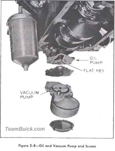
The oil pump driven gear drives the vacuum pump rotor by means of a flat key which extends down through the common pump cover plate.
| Shaft to Bearing Clearance | .001" - .0025" |
| Idler Gear Bearing Clearance | .001" - .0025" |
| Drive Gear Backlash | .002" - .004" |
| Drive to Idler Gear Backlash | .004" - .008" |
| Gear End Clearance in Body | .005" |
1. Remove vacuum pump housing with end cover, then remove the oil pump shaft and gear, and idler gear from the pump body.
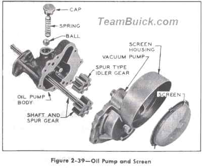
2. Remove hex cap , spring, and pressure ball from pump body.
3. Thoroughly wash the screen and pump parts in solvent and blow dry with air hose.
4. Check oil pressure regulator ball to see if it is free in pump body. Also check hole in body to see that it is not oversize and that the ball fits hole throughout length. Check spring to see that it is not collapsed, worn on its side , or broken.
5. Inspect pump body, cover, gears, and shaft for wear, scoring , etc., and replace any unserviceable parts.
6. Install gear and shaft assembly in pump body and install idler gear with vacuum pump driving grooves toward pump cover.
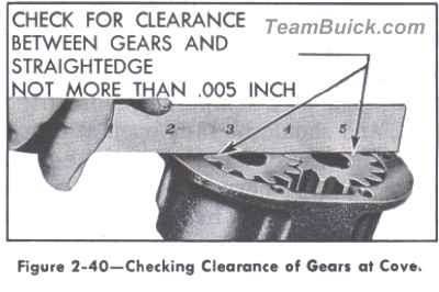
7. Check for clearance between gears and cover by using a steel straight edge and feeler gages. The clearance between straight edge and gears should be such that the gears turn freely and must not be more than .005".
8. Assemble parts to pump body by reversing sequence of removal given in steps 1 and 2. After all screws are tightened, turn the shaft by hand to make sure that it turns freely and has a slight amount of end play (.0005' to .005").
9. Before installation of oil pump, check crankcase and pump body for dirt or burrs that might tilt the pump and cause binding.
10.Install oil and vacuum pump assembly with a new gasket, tightening attaching bolts alternately a little at a time. Check alignment by rotating pump shaft with screwdriver through distributor mounting hole.
If pump shaft tends to bind when bolts are evenly tightened, it may be freed up by rapping pump body lightly with a rawhide mallet. Pump shaft must be free of bind when bolts are securely tightened.
Vacuum pumps are serviced only as complete assemblies. If severe damage to vacuum pump is encountered, it is recommended that the oil pump idler gear and driving key be inspected before replacing vacuum pump.