"Buick Trademark(s) used with the written permission of General Motors"

Pg 105
ENGINE CONVERSIONS
All the dope you will need to make your car into a real "bomb", whether you own a Buick, Chevy, Chrysler product, Ford 6 or V-8, GMC, Hudson, Mercury or Pontiac
IN THIS SECTION, we will discuss specific engine conversions of a few of the more popular makes. The engines described here may be used strictly for competition, because the methods outlined in Sections III and V may be used, generally, for any engine in the "medium" and "hot" transportation classification. Where specific information is lacking in the previous sections, it has been included here, as necessary. The specific engine conversions discussed here will, of necessity, be quite brief and to the point, with a minimum of theorizing. It will be assumed in all cases that the engine has been removed from the chassis and has been completely disassembled and properly cleaned.
Buick Three engine sizes are now available in this make. The small engine has a bore and stroke of 3 3/32 and 4 1/8 inches, respectively, with a capacity of 248 cubic inches and has been manufactured from 1937 to the present time with minor modifications. The second engine size is 263 cubic inches using a bore of 3 3/16 inches and a stroke of 4 1/8 inches. These have been in production since 1950. The largest engine measures 320 cubic inches and has a bore of 3 7/16 inches and a stroke of 4 5/16 inches and has been manufactured from 1937 ( sic, actually 1936 ) to the present time. The three engines are of similar construction throughout and the modifications described are applicable to all three.
The cylinder bore on these engines may be enlarged .125 of an inch oversize, without fear of "falling through" into the surrounding water jacket. This would give a bore size of 3 7/32 inches on the small engine and results in 268 cubic inches. The second engine is, to all intents and purposes, a bored out version of the small engine. These should be carefully examined to see how much over boring is practicable. The largest engine may be safely bored to 3 7/16 inches and gives 343 cubic inches. In one instance, Don Montgomery's competition Buick-Cord sedan, the bore has been increased to 3 5/8 inches, raising the displacement to 356 cubic inches. For most purposes the bore size should be kept below this figure.
Stroking the crankshafts on these engines is of quite doubtful value and it is recommended that the stock stroke be used. Pistons for these engines should be the solid skirt, racing type if compression ratios over 8.5 to 1 are used, because the stock-type pistons are of insufficient strength under the crown, and collapsed piston crowns sometimes result. Racing-type pistons of either flat heads or "turbulator" heads for either crankshaft stroke are available, and the cost is between $75.00 and $80.00 per set, with wrist pins. Stock wrist pins, however, are quite satisfactory and should be a palm-push fit through the wrist pin bore in the piston at room temperature. The two smaller engines have wrist pins .8127 of an inch in diameter.
Pistons must be assembled on the connecting rods so that the oil hole in the connecting rod and the hollow side of the piston head are on the same side ( "turbulator" pistons only ). The wrist pins are clamped in the small end of the rod and care must be exercised when tightening the wrist pin clamp bolt, to prevent the wrist pin from binding in the piston. These bolts should be torqued to 25 to 30 foot pounds.
Engines made prior to 1949 had poured Babbitt-type connecting rod bearings with shims used for adjustment, to compensate for wear. Engines made after 1949 use a more conventional steel-backed insert with a thin layer of bearing material. A thin bearing shell of this type can carry higher bearing loads and dissipate the heat generated better than a thick layer of bearing material bonded to the connecting rod and connecting rod cap. The late-type connecting rods and bearings are interchangeable with the earlier type, and it is recommended that this change be made. After the pistons have been installed on the connecting rods, the alignment should be checked and
Pg 106
corrected as necessary on a suitable rod aligning plate.
The Buick crankshaft has five main bearing journals of quite large diameter. The journal diameters become larger from the front to back, except in the 263 cubic inch engine, in which case they are of constant diameter ( 2.562 inches ). To prevent misalignment of the crankshaft, matched sets of main bearing inserts must be installed when fitting the crankshaft to the block. Factory quality main bearing inserts should be used and factory specified main bearing clearances, made by shimming the main bearing cap, are satisfactory for converted engines. Factory quality connecting rod bearing inserts are recommended and it is advisable to increase the connecting rod bearing clearance to .003 of an inch. If the crankshaft must be ground to an undersize main bearing journal or crank pin diameter, it is suggested that the crankshaft be rebalanced. The balancing unit on the front of the crank is for torsional oscillation damping, and will not counteract any unbalanced weights. The crankshaft should be soaked in a degreasing solution followed by steam cleaning, special attention being given to the the oil passages to insure cleanliness. Main bearing bolts must be torqued to 90 to 100 foot pounds. Crankshaft end play should be from .004 to .008 of an inch and may be increased by scraping the thrust surface of the center main bearing. Factory-type main bearing oil seals should be installed in the block and rear main bearing cap.
Connecting rod bolts are of a special diameter to insure correct alignment between the connecting rod and connecting rod cap, and no other bolt type may be used. Connecting rod bolt nuts must be torqued to 40 to 45 foot pounds on the small engine, and 60 to 65 foot pounds on the large engine, using Pal nuts or cotter pins, as required, to prevent the connecting rod nuts from working loose. The hollow side of the piston head and the oil hole in the lower end of the connecting rod must face the camshaft side of the engine.
The camshaft is installed without the camshaft sprocket. The sprocket and timing chain are installed by slipping the chain over the crank and cam sprocket and placing the cam sprocket on the camshaft. Valve timing is assumed to be correct when the two links, with copper plated washers on the outer edge of the chain, are in mesh with the sprocket teeth that are punch-marked. The marked links must be on the driver's side of the engine. The cam sprocket is then put in place with a cap screw and lock washer. The timing chain cover oil seal should be replaced with a new one and the sharp edge of the leather must face the rear of the engine. Installation of the cover and torsional oscillation damper should wait until the valve timing is accurately set.
Pressure lubrication comes from a positive displacement gear pump that must be disassembled and fully cleaned. Normal operating oil pressure is about 35 psi at 35 mph and is sufficient for converted engines.
The flywheel weight may be reduced by removing metal from the front and back surfaces of the flywheel, without cutting into the clutch surface. Sufficient material must be left in the thickness of the flywheel so the strength will not be affected. Buick diaphragm-type clutch pressure plates are not satisfactory and should be replaced with a Borg and Beck number 4050 replacement pressure plate. A new ( not rebuilt ) factory-type clutch plate is recommended and will stand up under severe usage. The flywheel and pressure plate assembly must now be dynamically balanced to insure smooth, vibrationless operation.
The Buick cylinder heads are provided with four Siamesed intake ports and eight exhaust ports, and the porting of the head, as referred to in Section V, should be applied here. However, the intake ports are quite thin, and care must be exercised to prevent "falling through" into the water jacket. In the large engine, the relatively small intake port size is one of the limiting factors of engine performance. New valve guides should be installed, but the height of the old guides must be measured first, and the new guides pressed in to the same depth. The guides must be reamed to .374 to .375 of an inch diameter after they are installed in the head. Intake guides may be cut of flush with the top of the intake port, and any burrs around the guide hole must be removed.
Due to the fact that no valve seat inserts are used, and the relatively soft material used in the head casting, valve seats must be made quite wide to prevent the valve seat from sinking into the head. Exhaust valve seats must be at least 1/8 of an inch wide and so located that the exhaust valve contacts the valve seat in the center of the seat area on the valve. Intake valves and valve seats may be refaced to 30 degrees instead of 45 degrees. The intake valve seat must be about 3/32 of an inch wide, and should contact the
Pg 107
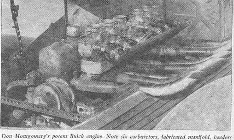
Don Montgomery's potent Buick engine. Note six carburetors, fabricated manifold, headers.
valve near the outside of the valve seat area, leaving about 1/64 to 1/32 of an inch between the upper valve seat face and the seat. The size and shape of the valves are quite satisfactory and the factory valves should be used for replacement. If a reground cam is used, valve spring tension should be increased by the addition of a 5/8 inch S.A.E. flat washer on each valve guide next to the cylinder head. The washer must be between the head and inner spring seat. These washers provide about 15 pounds increase when the valve is seated. Valve stem tips that show any signs of wear must be ground square with the valve stem. Rocker arm bushings and shafts should be checked for wear and replaced if necessary. The surface of the rocker arm that contacts the valve stem may be ground if it is worn, but must be ground on a suitable machine to assure the proper radius.
Pre-1948 camshafts, cam followers ( tappets ) and push rods are quite satisfactory for converted engines. In some engines built since 1948, hydraulic-type cam followers ( ed - lifters ) were used, and this arrangement is not satisfactory in an engine of this type. It is recommended that hydraulic cam followers and push rods be replaced with the earlier type. Camshafts used with hydraulic cam followers cannot be used with solid cam followers and must either be reground or replaced. Rocker arm assemblies are quite satisfactory and may be used "as is".
Cylinder heads may be milled as much as .175 of an inch but clearances must be checked, as outlined in Section III, to prevent the piston from striking the head. Milling this much from the head increases compression ratio considerably and should only be done when the engine is to be used with either 100 octane gasoline or alcohol for fuel. The combustion chamber surface should be ground and polished to eliminate the hot-spots that cause detonation. There are two head gasket thicknesses available for Buick engines, one being .050 of an inch and the other .015 of an inch. Either may be used in combination with milling the head. The maximum for city driving, using premium gas seems to be milling the head .100 of an inch and using the thin gasket.
There are no intake manifolds available for use with three or more carburetors for Buick engines, but if the builder desires, a manifold for any number of carburetors may be fabricated easily. Four Stromberg Model 97 or 48 carburetors work well on gas and four Buick Strombergs are satisfactory for alcohol after they have been converted for this fuel. Four 90-degree elbows can be fabricated from steel tube of a suitable diameter with flanges made from ¼ of an inch thick steel plate. Equalizer passages should be provided between each elbow and should be at least ½ inch in diameter. Manifolds for more than four carburetors must be made in the form of a "log", using three inch diameter steel tube or 1½ x 3 inches rectangular section steel tube.
Camshafts of stock Buicks are quite mild, and a considerable performance increase can be gained by installing a reground camshaft. Some of the more radical Chevrolet and GMC valve timings have been found to be successful.
At the present time, there is only one good, consistent performing Buick competition engine in the Southern California area, belonging to Don Montgomery. This car performs as well at the drag races as at the
Pg 108
dry lakes and is the present "B" Sedan Class record holder in the Russetta Timing Association. The engine is equipped with a reworked stock head, Scintella Vertex magneto, and a six-carburetor fabricated manifold that uses six model 48 Stromberg carburetors converted for alcohol. The horsepower output of this engine is estimated to be 270 to 280 and represents the possibilities in a Buick engine conversion. As with any engine conversion, the quality of workmanship and parts used will determine the success of the project.