"Buick Trademark(s) used with the written permission of General Motors"

a. On 45000, 46000 and 48000 Series, move the WARMER lever a short distance forward from the off position. There should be no vacuum to the vacuum diaphragm of the valve.With the WARMER lever in this position, the evaporator pressure should raise by approximately three psi. If the evaporator pressure does not increase, check the water valve and STV vacuum disc switch, improper vacuum hose
Removal and Installation of Suction Throttle Valve 1. Discharge refrigerant from system as described in subparagraph "c".connections or kinked vacuum hoses. If these are correct, the suction throttle valve is defective and should be repaired.
b. On 49000 Series, move the Air Conditioner Air Control lever to normal position and the temperature control and Fan switch levers to Low.With the levers in this position, the evaporator should raise to approximately 50 psi. Return the levers to full on and recheck setting of the suction throttle valve.
If the 49000 evaporator pressure does not increase when Air Conditioning Temperature Control and Fan lever are at Low, check operation of vacuum modulator by connecting a vacuum gauge to the hose that goes to the STV. The modulator should regulate manifold vacuum from 6 to 7 inches when the temperature control lever is moved from the Low position to 0 inches when the temperature control and Fan switch levers are respectively in the cooler and high position. If modulator does not function properly, check vacuum hose connections, check for kinked hose or for defective modulator.
NOTE: All of the openings to the air conditioning system should be capped or plugged during the time the STV is removed.
4. Install valve by reversing procedure for removal, paying attention to the following: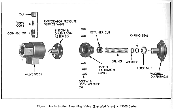
to prevent piston from sucking on initial operation.Disassembly and Assembly of Suction Throttle Valve
(c) Evacuate and charge the system. Leak test valve and connections. Correct any leaks.
(d) After system has been charged, on 49000 move air conditioning temperature control lever from one extreme to the other about 12 times with system operating to normalize the valve diaphragm.
(e) Check operation of the suction throttle valve, refer to subparagraph "f".
If test indicated suction throttle va1ve 1s defective, the valve should be overhauled as follows:
1. With valve removed from car, loosen lock nut on vacuum diaphragm and turn diaphragm assembly out of cover. On 49000 valve, discard "0" ring on sleeve of diaphragm. See Figure 11-91.
2. Remove spring from cover.
3. Remove the five screws that retain cover to body of valve and remove cover.
4. Remove diaphragm and piston assembly.
5. Remove retainer cup from diaphragm.
The diaphragm should be handled with care to avoid damage by scuff1ng, cutting or abrading the rubber and fabric surfaces. The piston dIaphragm or the screen and retainer in the lower portion of the piston should not be removed. The screen should, however, be examined for any foreign material or contamination. If necessary clean screen with a volati1e solvent. All solvent should be removed from parts after cleaning.
In the event the exterior surface of the piston is damaged such as scored,
scratched or nicked, in such a way as to cause it to bind in the bore, it should be replaced.
NOTE: Examine the body bore surfaces for any surface imperfections, foreign material and any obvious damage that would cause the piston to not operate freely. The body should be replaced if the bore is damaged or if any cross threading or damage has been sustained around the connector parts.
6. Apply a light coat of 525 viscosity oil to the wall of the piston and insert it into the body of the valve.Carefully push the piston into the cover so that the diaphragm positions properly into the cavity of the cover and does not become pinched under the flange.
Remove the rod from the inlet opening and insert it through the upper portion of the cover. It should contact the center post of the cup. Press lightly downward so as to cause the piston to seat against the inner shoulder of the body. While the cup, diaphragm and piston are held down, tighten the five screws to 45 to 50 inch pounds torque.
9. Place locknut on vacuum diaphragm and install a new "0" ring on diaphragm.NOTE: The 45000, 46000 and 4BOOO Series valve diaphragm does not use an "0" ring.
10. Insert washer and spring in vacuum diaphragm.