"Buick Trademark(s) used with the written permission of General Motors"

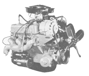
General Specifications for the 198 and 225 Cubic Inch V-6. The following information has been directly complied from original Buick service manuals.
| Area | Lb. Ft. |
| Crankshaft Bearing Caps to Cylinder Block | 95-120 |
| Connecting Rods | 30-40 |
| Cylinder Head to Cylinder Block | 65-80 |
| Fan Driving Pulley to Harmonic Balancer | 18-25 |
| Flywheel to Crankshaft (Auto. & Manual) | 50-65 |
| Oil Pan to Cylinder Block | 9-13 |
| Oil Pan Drain Plug | 25-35 |
| Oil Pump Cover to Timing Chain Cover | 8-12 |
| Oil Pump Pressure Regulator Retainer | 25-30 |
| Oil Screen Housing to Cylinder Block | 6-9 |
| Oil Pan Baffle to Cylinder Block | 9-13 |
| Oil Gallery Plugs | 20-30 |
| Filter Assembly to Pump Cover | 10-15 |
| Timing Chain Cover to Block | 17-23 |
| Water Pump Cover to Timing Chain Cover | 6-8 |
| Fan Driven Pulley | 17-23 |
| Thermostat Housing to Intake Manifold | 17-23 |
| Intake Manifold to Cylinder Head | 45-55 |
| Exhaust Manifold to Cylinder Head | 10-15 |
| Carburetor to Intake Manifold | 10-15 |
| Air Cleaner Stud | 17-23 Lb. In. |
| Air Cleaner Wing Nut | 17-23 Lb. In. |
| Fuel Pump to Cylinder Block | 17-23 |
| Motor Mount to Cylinder Block | 50-75 |
| Fuel Pump Eccentric and Timing Chain Sprocket to Camshaft | 40-55 |
| Rocker Arm Cover to Cylinder Head | 3 to 5 |
| Rocker Arm Shaft Bracket to Cylinder Head | 25-35 |
| Delcotron Bracket to Cylinder Head | 30 to 40 |
| Delcotron Bracket to Water Pump Timing Chain Cover | 18-25 |
| Delcotron Mounting Bracket thru Delcotron to Cylinder Head at Pivot Location | 30-40 |
| Starting Motor to Block | 30-40 |
| Starting Motor Brace to Block | 9-13 |
| Starting Motor Brace to Starting Motor | 9-13 |
| Distributor Hold down Clamp | 10-15 |
| Spark Plugs | 25-35 |
| Manual Lower Flywheel Housing | 9-13 |
| Flywheel Housing to Cylinder Block | 30-40 |
| Timing Chain Damper to Cylinder Block Bolt | 6-9 |
| Bolt - Special Moveable Timing Chain Damper | 10-15 |
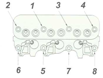 Buick 225 head bolt torque pattern.
| GENERAL SPECIFICATIONS | |
| Engine Type | 90° V-6 |
| Valve Arrangement | In Head |
| Bore and Stroke | 3.750 x 3.400 |
| Piston Displacement | 225 Cu. In. |
| Compression Ratio | 9.0 to 1 |
| Brake Horsepower @ RPM | 160 BHP @ 4400 |
| Torque § RPM | 225 Lb. Ft. @ 2400 |
| Octane Requirement | 85 Motor Method |
| Octane Requirement | 93 Research Method |
| Taxable Horsepower | 33.748 |
| Cylinder Numbers Front to Rear Right Bank | 2-4-6 |
| Left Bank | 1-3-5 |
| Firing Order | 1-6-5-4-3-2 |
| Cylinder Block Material | Cast Iron |
| Cylinder Head Material | Cast Iron |
| Engine Idle Speed | |
| .....Manual | 550 |
| .....Automatic | 550 Drive |
| .....AC Auto | 600 Drive |
| Piston and Piston Pin Specifications | |
| Piston Material | Cast Aluminum Alloy |
| Piston Treatment | Tin Plated |
| Piston Pin Material | SAE 1018 |
| Piston Pin Type | Pressed In Rod |
| Connecting Rod Specifications | |
| Material | Pearlitic Malleable Iron |
| Bearing Type | Removable Steel Backed |
| Bearing Material | M100 Durex |
| Rod Length | 5.960 |
| Rod Width | .835 |
| Ring Specifications, Compression Ring Material & Surface Treatment | #1 | Iron - Chrome Plated |
| #2 | Iron - Lubricated |
| Oil Ring Type | Dual Steel Rail with Spacer |
| Oil Ring Expander | Steel Humped Ring |
| Location of Rings | Above Piston Pin |
| Crankshaft Specifications | |
| Material | Pearlitic Malleable Iron |
| Bearings | 4 Replaceable Liner |
| Bearing Material | M100 Durex |
| Bearing Taking End Thrust | #2 |
| Camshaft Specifications | |
| Material | Cast Alloy Iron |
| Bearings | Steel Backed Babbitt |
| Number of Bearings | 4 |
| Camshaft Location | Above Crankshaft at Center of "V" |
| Type of Drive | Chain |
| No. of Links | 54 |
| Crankshaft Sprocket | Sintered Iron |
| Camshaft Sprocket | Nylon Coated Aluminum |
| Valve Specifications | |
| Intake Valve Material | SAE 1041 Steel |
| Exhaust Valve Material | GM-N82152(21-4N) |
| Valve Lifter Type | Hydraulic |
| Valve Spring | Single Helical |
| Lubrication System Specifications | |
| Type of Lubrication Main Bearings | Pressure |
| Connecting Rods | Pressure |
| Piston Pins | Splash |
| Camshaft Bearings | Pressure |
| Timing Chain | Splash & Nozzle |
| Cylinder Walls | Splash & Nozzle |
| Oil Pump Type | Gear Driven |
| Normal Oil Pressure | 33 Ibs. @ 2400 RPM |
| Oil Pressure Sending Unit | Electrical |
| Oil Intake | Screened Tube |
| Oil Filter System | Full Flow |
| Filter Type | Throw-Away Element & Can |
| Crankcase Capacity Less Filter | 4 qts. |
| With Filter | 5 qts. |
| Cooling System Specifications | |
| System Type | Pressurized Utilizing Cross-Flow Radiator |
| Radiator Cap Relief Pressure | 15 psi |
| Thermostat | Choke Type Opening at 180° |
| Water Pump Type | Centrifugal |
| GPM @ RPM | 14@1000 |
| Drive | V-Belt |
| Bearings | Double Row |
| By-Pass Recirculation Type | External |
| Cooling System Capacity With Heater | 11.2 qts. |
| W/O Heater | 10.5 qts. |
| With AC | 11.2 qts. |
| Fan Diameter and Number of Blades | |
| Less AC | 17" - 4 |
| With AC | 18" - 7 |
| Fan Drive Less AC | Water Pump Shaft |
| With AC | Torque and Temperature Sensitive Clutch |
| ENGINE DIMENSIONS AND FITS | |
| Deck Height | 10.187 |
| Rings, Piston, and Piston Pin Specifications | |
| Piston Clearance Limits | |
| ....Top Land | .0265" - .0345" |
| ....Skirt - Top | .0005" - .0011" |
| ....Skirt - Bottom | .0005" - .0021" |
| Ring Groove Depth | |
| ....#1 - Compression Ring | .1855" - .1930" |
| ....#2 - Compression Ring | .1880" - .1955" |
| ....#3 - Oil Ring | .1880" - .1955" |
| Ring Width | |
| ....#1 - Compression Ring | .0785" - .0790" |
| ....#2 - Compression Ring | .0770" - .0780" |
| ....#3 - Oil Ring | .1810" - .187" |
| Ring Gap | |
| ....#1 - Compression Ring | .010" - .020" |
| ....#2 - Compression Ring | .010" - .020" |
| ....#3 - Oil Ring | .015" - .035" |
| Piston Pin Length | 3.060" |
| Diameter of Pin | .9394" - .9397" |
| Clearance | |
| ....In Piston | .0001" - .0004" |
| ....In Rod | .0007" - .0015" |
| Press Direction & Amount Offset in Piston .040" Toward High Thrust Side | |
| *A11 Measurements in Inches Unless Otherwise Specified. | |
| Connecting Rod Specifications | |
| Bearing Length | .737" |
| Bearing Clearance (Limits) | .0020" - .0023" |
| End Play - Total for both Rods | .006" - .014" |
| Crankshaft Specifications | |
| End Play at Thrust Bearing | .004" - .008" |
| Main Bearing Journal Diameter | 2.4995" |
| Crank pin Journal Diameter | 2.0000" |
| Main Bearing Overall Length | |
| ....#1 | .864" |
| ....#2 | .1057" |
| ....#3 | .864" |
| ....#4 | .864" |
| Main Bearing to Journal Clearance | .0005" - .0021" |
| Camshaft Specifications | |
| Bearing Journal Diameter | |
| ....#1 | 1.755" - 1.756" |
| ....#2 | 1.725" - 1.726" |
| ....#3 | 1.695" - 1.696" |
| ....#4 | 1.665" - 1.666" |
| Journal Clearance in Bearings | |
| Valve System Specifications | |
| Rocker Arm Ratio | 1.6 to 1 |
| Rocker Arm Clearance On Shaft | .0017" - .0032" |
| Valve Lifter Diameter | .8422" - .8427" |
| Valve Lifter Clearance in Crankcase | .0015" - .003" |
| Valve Lifter Leak down Rate | 12 to 60 Sec. in Test Fixture |
| Intake Valve | |
| Head Diameter | 1.625" |
| Seat Angle | 45° |
| Stem Diameter | .3412" Top - .3407" Bottom |
| Clearance in Guide | Top .001"-.003" - Bottom .0015"-.0035" |
| Stem Height | 1.8450-1.8750" |
| Exhaust Valve | |
| Head Diameter | 1.3750" |
| Seat Angle | 45° |
| Stem Diameter | 3407" Top - .3402" Bottom |
| Clearance in Guide | Top .0015"-.0035" - Bottom .002"-.004" |
| Installed Stem Height | 1.8450-1.8750" |
| Valve Spring | |
| Valve Closed - Pounds @ Length | 64 ± 5 @ 1.727" |
| Valve Open - Pounds @ Length | 164 ± 6 @ 1.340" |
| Cubic Inches | V-225 | V-198 | V-231 |
| Bore | 3.750 | 3.625 | 3.800 |
| Stroke | 3.400 | 3.200 | 3.400 |
| Rod Length | 5.960 | - | 5.960 |
| Rod / Stroke Ratio | 1.7529 | - | - |
| Bore / Stroke Ratio | 1.1029 | - | - |
| Bore Spacing | 4.240 | - | - |
| Deck Height | 10.187 | 10.187 | 9.535 |
| Comp. Distance | 1.870 | 1.844-1.860 | - |