

If you go to the Reference section, there is a complete '66 Chassis Manual with wireing diagrams and you will also find a charging system diagnosis in the manual too.

 Junior Member

Hi , i need help because i have a failure of battery charging on my 1966 Buick Riviera GS : the battery don't charge but :the battery is a new one and is OK , the altrenator has been tested by a specialist : it works fine ; the regulator is a new one , that was changed the last year . I tested the cables that go from the alternator to the régulator , ( a dark blue and a red one ) , they are OK . By cons there is a third cable connected to the régulator , ( a yellow one ) ,and i can not know what this cable is connected , so that i can't test it . I own the wiring circuit diagrams ( in the chassis service Manual ) , but i can't see where goes this cable because the color is to light .
I tried to see if it was connected to the battery and it appears that this cable has a connection with the negative plug of the battery :
is this connection normal ? How can i test the régulator ? Thank you for your help . Bertrand .


If you go to the Reference section, there is a complete '66 Chassis Manual with wireing diagrams and you will also find a charging system diagnosis in the manual too.
Members can be contacted by clicking on their "handle", but you are much better off to post to the thread!
Senior Member
Bert, lemme ask a question; how did the wiring get disconnected - wasn't the Rivvy running when you had this problem?
there shouldn't be any other wires connected to the battery cept the #00 black ground to block and the #8 (maybe a #10) from the negative post to the body - usually on the front cross member. then a red #00 positive wire to the horn relay terminal (which is where all the positives extend from), plus a red #10 that goes to the alternator.
Isn't there four posts on the Rivvy regulator?
I was just looking at the wiring diagram for the Wildcat -
lemme see if I can call it up again. I suffer from forgetsalot
I think the yellow goes to the
Junior Member
Hi , thank you for your answers , i had a look to the reference section
but i didn't found the wiring diagram and the trouble diagnosis procedure in the chassis manual , can you tell me the page number where i can find the informations ?
Regarding the regulator , it has four ports but only three are connected : one red ( positive ) , one darkblue ( ? ) and one yellow ( ? ) . I don't really understand how it works so i 'm interested in all iformations about the cables and the way of working . Thank you , Bertrand .
Senior Member
Bert, is that a 3 wire alternator or single wire?
Junior Member
The alternator has two wires ( one red , one dark blue) , on the back , there is a port named " ground " were you can connect a wire , but it is not used .
Senior Member
NOTE: the diagram is for an alternator with a built in regulator - I hope you can work with it
Bert... I made one correction to the explaination (it says a "red" wire comes off #2 pin on the alternator. actually, there should be 4 wires coming from the Regulator: the Positive Red charging wire, a Blue & a White that comes from the middle two pins on the regulator and attach to the alternator by a two prong connector, the 4th wire (mine is brown) from the alternator should enter the firewall via a large connecting plug just under the brake booster or master cylinder - if you don't have power brakes. it turrns around and comes out yellow - and goes to the starter.
YOU should be able to "Google" any question you have and you will get tons of advice/charts/diagrams.
- I just googled "wiring for 66 Rivera Alternator"...
I've learned tons of stuff about Buicks that I never thought about - until I had one or two sitting in my garage.
As you will read, it is prudent to connect the ground on the alternator to the block using a #10 black wire
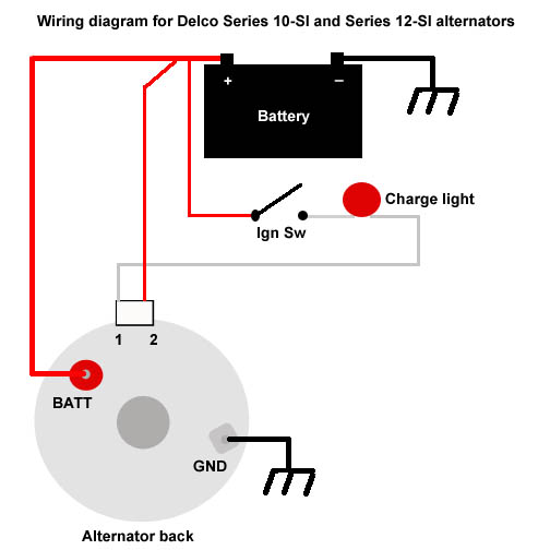
Batt
(Red AWG #10 or #8 wire going to insulated terminal at rear of alternator) This terminal is for the alternator output to the battery. On Land Rovers equipped with an ammeter this lead goes directly to the ammeter POS terminal. The ammeter NEG side goes to the battery positive terminal, usually by being connected to the starter switch or relay. A 10 gauge wire will work for all the 10-SI alternators and the low to mid amp 12-SI alternators. The high amp 12-SI should get a AWG #8 wire. You should install a fusible wire link in this wire in case of an accidental short to keep the shorted wire connected directly to the battery from starting a fire. The fusible link should be placed near the battery.
1 "Excite"
(White AWG # 14 or #16 wire on white molex plug) This wire provides the start up voltage for the alternator. The "1" alternator terminal is fed by a switched 12V source from the ignition switch through a lamp ("idiot light") and is used to supply the magnetic field inside the alternator with the voltage needed to operate. The alternator can not start charging until there is a voltage on the field winding and a magnetic force is created.
The idiot light is there to act as a visual indicator of under voltage and over voltage conditions at the battery. When the engine is running, if the idiot light is on, the output voltage of the alternator is out of specification.
2 "Sense"
(Blue AWG #10 or #12 wire on white molex plug) The 'Sense' wire checks the voltage output level of the alternator. This is the reference voltage that the alternator uses to determine how much power to put out. If the sensed voltage gets higher than the regulator is adjusted for, the regulator causes the alternator to momentarily stop charging until the sensed voltage drops down to a specified amount, then the alternator resumes charging. The regulator basically turns the alternator on and off fast enough to keep the output voltage within a specified voltage range.
The Number two "sense" terminal is often connected to the BATT. terminal at the back of the alternator. This is the simplest connection and the least desirable since it is measuring the alternator output and not the voltage at the load connections. Any voltage drop due to loose, dirty or corroded connections and internal resistance of the wires and components is not accounted for and the voltage at the circuit loads may be lower than it should be. The voltage is best sampled in the interior of the vehicle after the fuse block load, where all the electrical current load of the vehicle is. The 'Sample' would better sense a voltage drain and and the alternator would correct for it.
Gnd
(Black AWG #10 or #8 wire going to screw on back case of alternator) When most people convert to a SI Series Delco alternator they leave off the ground wire and rely upon the alternator mounting bolts, engine block and engine to ground strap for an alternator return path. This works just fine most of the time as long as the mounting bolts are making a good electrical connection. Sometimes the ground connection may not be all that good or it may get worse over time. This higher resistance connection keeps the alternator from generating its full rated amperage. An AWG #10 or #8 gauge wire between the alternator ground connection and a good frame ground assures a good pathway for the alternator. This wire should have a fusible link in case your engine to frame ground strap fails and tries to route all the starter current through the alternator ground wire.
Some common fault symptoms and what they most likely indicate:
- AM radio interference, bad rectifiers.
- Battery discharges overnight, bad rectifiers
- Charging voltage below 13V above 2000 engine RPM alternator likely not working. Pull alternator and take down to shop to be tested.
- Idiot light does not come on when key on and engine not running, bad bulb or electrical connection.
- Stop vehicle & check immediately If not belt look for a connection that just came off. Your alternator has stopped charging. If nothing obvious can be found, pull alternator and have it checked on a machine.
- Idiot light on very dimly. Alternator charging but not enough to keep up with current drain produced by vehicle electrics
Last edited by WildKitty; 08-01-2010 at 09:20 PM. Reason: left off sentence
If that doesn't help, trouble shooting is on page 68-9
http://www.teambuick.com/reference/l...assis/68-a.pdf
Members can be contacted by clicking on their "handle", but you are much better off to post to the thread!
 Posting Permissions


Bookmarks