"Buick Trademark(s) used with the written permission of General Motors"

General Specifications for the 1966 Buick 401 and 425 Cubic Inch Engines The following information has been directly complied from original Buick service manuals for the respective year of vehicle manufacture. These specifications should also be correct for the 1966 model year.
Use a reliable torque wrench to obtain the figures listed below. This will prevent straining or distorting the parts as well as preventing thread damage. These specifications are for clean and lightly lubricated threads only. Dry or dirty threads produce friction which prevents accurate measurement of the actual torque. It is important that these specifications be strictly observed. Over tightening can damage threads. This will prevent attainment 'of the proper torque and will require replacement of the damaged part.
| Area | Lb. Ft. |
| Spark Plugs | 25-35 |
| Crankshaft Bearing Caps to Cylinder Block | 80-110 |
| Connecting Rods | 40-50 |
| Cylinder Head to Cylinder Block | 65-80 |
| Harmonic Balancer to Crankshaft | 200 Minimum |
| Fan Driving Pulley to Harmonic Balancer | 18-25 |
| Flywheel .to Crankshaft (Auto. & Manual) | 50-65 |
| Oil Pan to Cylinder Block | 9-13 |
| Oil Pan Drain Plug | 25-35 |
| Oil Pump Cover to Oil Pump | 8-12 |
| Oil Pick-Up Tube & Screen Housing Assembly to Oil Pump | 6-9 |
| Oil Pump to Cylinder Block | 30-40 |
| Oil Gallery Plugs | 25-35 |
| Oil Filter to Cylinder Block | 10-15 |
| Timing Chain Cover to Block | 17-23 |
| Water Pump Cover to Timing Chain Cover | 6-8 |
| Fan Driven Pulley | 17-23 |
| Thermostat Housing to Intake Manifold | 17-23 |
| Intake Manifold to Cylinder Head | 25-35 |
| Exhaust Manifold to Cylinder Head | 10-15 |
| Carburetor to Intake Manifold | 10-15 |
| Fuel Pump to Cylinder Block | 25-40 |
| Motor Mount to Cylinder Block | 25-40 |
| Fuel Pump Eccentric and Timing Chain Sprocket to Camshaft | 40-55 |
| Rocker Arm Cover to Cylinder Head | 3-5 |
| Rocker Arm Shaft Bracket to Cylinder Head | 25-35 |
| Delcotron Bracket to Cylinder Head | 65-80 |
| Delcotron Bracket Brace | 18-25 |
| Delcotron Adjustable Mounting Bracket to Cylinder Head | 25-40 |
| Delcotron Mounting Bracket Thru Delcotron to Cylinder Head at Pivot Location | 35-45 |
| Starting Motor to Block | 40-55 |
| Distributor Hold-Down Clamp | 10-15 |
| Synchromesh Lower Flywheel Housing Plate | 9-13 |
| Flywheel Housing to Cylinder Block | 45-60 |
| Fuel Filter to Cylinder Head | 7-10 |
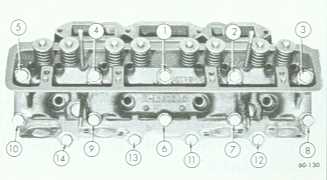 Buick Nailhead head torque pattern. |
|
| General | ||
| Wildcat 445 (400 & 401 Co. In.) |
Wildcat 465 (425 Cu. In.) |
|
| Code Number Prefix | MR (400), MT (401) | MW |
| Export Code Number Prefix | MV | Not Available |
| Engine Type | 90° V-8 | 90° V-8 |
| Bore and Stroke | 4.1875 x 3.640 | 4.3125 x 3.640 |
| Piston Displacement | 400 & 401 Cu. In. | 425 Cu. In. |
| Carburetor Type | 4 Bbl. | 4 Bbl. |
| Compression Ratio | 10.25:1 | 10.25:1 |
| Gasoline Requirements | Premium | Premium |
| Brake Horsepower @ RPM | 325/4400 | 340/4400 |
| Maximum Torque @ RPM | 445/2800 | 465/2800 |
| Taxable Horsepower | 56.11 | 59.51 |
| Octane Requirements - Motor | 90 | 90 |
| Octane Requirements - Research | 99 | 99 |
| Cylinder Numbers - Front to Rear - Left Bank | 2-4-6-8 | 2-4-6-8 |
| Cylinder Numbers - Front to Rear - Right Bank | 1-3-5-7 | 1-3-5-7 |
| Firing Order | 1-2-7-8-4-5-6-3 | 1-2-7-8-4-5-6-3 |
| Piston and Pin Specifications | |
| Piston Material | Cast Aluminum Alloy |
| Type | Divorced Skirt |
| Finish | Cam Ground |
| Piston Pins | |
| Material | Extruded SAE-1018 |
| Type | Pressed in Rod |
| Connecting Rods | |
| Length | 6.220" (401/425) |
| Material | Forged - SAE-1141 Steel |
| Rod Bearing | Removable Steel Backed M/400 |
| Ring Specifications | |
| #1 Compression | Cast Iron-Lubrited |
| #2 Compression | Cast Iron-Lubrited |
| Oil Control | Steel-Uncoated |
| Oil Ring Expander | Steel Humped Ring |
| Ring Locations | Above Pin |
| Crankshaft Specifications | |
| Material | SAE-1145 or SAE-1053 Steel |
| Bearings | 5 Replaceable Steel Backed |
| Bearing Material | #1, #2, #3, and #4 - M/400, #5 - 100A Durex |
| Bearing Taking End Thrust | #3 |
| Deck Height | 10.00 |
| Camshaft Specifications | |
| Material | Cast Alloy Iron |
| Bearings | Steel Backed Bobbitt |
| Number of Bearings | 5 |
| Drive | Chain |
| Number of Links | 52 |
| Crankshaft Sprocket | Sintered Iron |
| Camshaft Sprocket | Nylon Coated Aluminum |
| Valve Specifications | |
| Intake Valve Material | SAE 1041 Steel, 1047 or TS 8150 Steel |
| Exhaust Valve Material | GM-N82152 (21 - 4N) |
| Valve Lifter Mechanism | Hydraulic |
| Valve Spring | Single Helical |
| Lubrication System Specifications | ||
| Type of Lubrication | ||
| Main Bearings | Pressure | |
| Connecting Rods | Pressure | |
| Piston Pins | Splash | |
| Camshaft Bearing | Pressure | |
| Timing Chain | Drip from Front Cam Bearing | |
| Cylinder Walls | Splash & Nozzle | |
| Oil Pump Type | Gear Driven | |
| Normal Oil Pressure | 40 Ibs. @ 2400 RPM | |
| Oil Pressure Sending Unit | Electrical | |
| Oil Intake | Stationary | |
| Oil Filter System | Full Flow | |
| Filler Type | Throw-Away Element & Can | |
| Crankcase Capacity | ||
| Less Filter | 4 qts. | |
| With Filter | 5 qts. | |
| Cooling System Specifications | |
| System Type | Pressure |
| Radiator Cap Relief Pressure | 15 psi |
| Thermostat | Choke Type Opening at 180° |
| Water Pump Type | Centrifugal |
| GPM @ RPM | 17 @ 1000 |
| Drive | V-Belt |
| Bearings | Double Row |
| By-Pass Recirculation Type | Internal |
| Cooling System Capacities | |
| With Heater | 18.0 qts. |
| W/O Heater | 17.0 qts. |
| With Air Conditioning | 18.27 qts. |
| Fan Diameter and Number of Blades | |
| Less AC | 18" x 4 |
| With AC | 20" x 5 |
| Fan Drive | |
| Less AC | Water Pump Shaft |
| With AC | Thermostatic Controlled Clutch |
| Engine Dimensions and Fits | ||
| Piston Clearance Limits* | ||
| 400 & 401 Cu. In. |
425 Cu. In. | |
| Top Land | .034 - .042 | .034 - .042 |
| Skirt - Top | .0004 - .0010 | .0004 - .0010 |
| Skirt - Bottom | .0019 - .0035 | .0019 - .0035 |
| Ring Groove | ||
| #1 - Compression Ring | .211 - .219 | .209 - .217 |
| #2 - Compression Ring | .214 - .221 | .212 - .219 |
| #3 - Oil Ring | .214 - .221 | .192 - .199 |
| Ring Width | ||
| #1 - Compression Ring | .077 - .078 | .077 - .078 |
| #2 - Compression Ring | .077 - .078 | .077 - .078 |
| #3 - Oil Ring | .181 - .187 | .182 - .1885 |
| Ring Gap | ||
| #1 - Compression Ring | .015 - .025 | .015 - .025 |
| #2 - Compression Ring | .015 - .025 | .015 - .025 |
| #3 - Oil Ring | .015 - .055 | .015 - .055 |
| Piston Pin Length | 3.520 | 3.520 |
| Diameter of Pin | .9994 - .9997 | .9994 - .9997 |
| Clearance | ||
| In Piston | .0001 - .0004 | .0001 - .0004 |
| In Rod | .00075 | .00125 Press |
| Direction & Amount Offset in Piston | None | None |
| *A11 Measurements in Inches Unless Otherwise Specified. | ||
| Connecting Rod Specifications | |
| Bearing Length | .820 |
| Bearing Clearance (Limits) | .0020 - .0023 |
| End Play-Total for Both Rods | .005 - .012 |
| Rod Length | 6.219 |
| Rod Width | .967 |
| Crankshaft Specifications | |
| End Play at Thrust Bearing | .004 - .008 |
| Main Bearing Journal Diameter | 2.4985 |
| Crank pin Journal Diameter | 2.2495 |
| Main Bearing Overall Length | |
| #1 | .940 |
| #2 | .940 |
| #3 | 1.127 |
| #4 | .940 |
| #5 | 1.200 |
| Main Bearing to Journal Clearance | .000 - .0019 |
| Bearing Journal Diameter | |
| #1 | 1.785 - 1.786 |
| #2 | 1.755 - 1.756 |
| #3 | 1.725 - 1.726 |
| #4 | 1.695 - 1.696 |
| #5 | 1.665 - 1.666 |
| Valve System Specifications | |
| Rocker Arm Ratio | 1.6 to 1 |
| Rocker Arm Clearance on Shaft | .0027 - .0042 |
| Valve Lifter Diameter | .8425 |
| Valve Lifter Clearance in Crankcase | .0015 - .0030 |
| Valve Lifter Leak down Rate | 12 to 60 Sec. in Test Fixture |
| Intake Valve | |
| Head Diameter | 1.875 |
| Seat Angle | 45° |
| Stem Diameter | (Top) 3.73 (Bottom) .372 |
| Clearance in Guide | (Top) .001 - .003 (Bottom) .002 - .004 |
| Valve Spring (Inner) | |
| Valve Closed - Pounds ° Length | 25.2 @ 1.690 |
| Valve Open - Pounds ° Length | 76 @ 1.250 |
| Valve Spring (Outer) | |
| Valve Closed - Pounds ° Length | 46 @ 1.600 |
| Valve Open - Pounds ° Length | 101 @ 1.160 |
| Exhaust Valve | |
| Head Diameter | 1.500 |
| Seat Angle | 45° |
| Stem Diameter | (Top) .372 (Bottom) .3715 |
| Clearance in Guide | (Top) .0015 - .0035 (Bottom) .0025 - .0045 |
| Valve Spring (Inner) | |
| Valve Closed - Pounds ° Length | 25.5 @ 1.690 |
| Valve Open - Pounds ° Length | 76 @ 1.250 |
| Valve Spring (Outer) | |
| Valve Closed - Pounds ° Length | 46 @ 1.600 |
| Valve Open - Pounds ° Length | 101 @ 1.160 |
| Installed Height | |
| Intake Valve | 1.900"-2.000"* |
| Exhaust Valve | 1.900"-2.000"* |
| * Measure next to valve in recess, or 1.540" from the rocker cover rail. | |
| Cubic Inches | 264 | 322 | 364 | 401 | 425 |
| Bore | 3.625 | 4.000 | 4.125 | 4.1875 | 4.3125 |
| Stroke | 3.203 | 3.203 | 3.391 | 3.640 | 3.640 |
| Rod Length | 6.000 | 6.000 | 6.100 | 6.220 | 6.220 |
| Rod Width | - | - | 0.967 | 0.967 | 0.967 |
| Rod/Stroke Ratio | 1.8732 | 1.8732 | 1.7989 | 1.7088 | 1.7088 |
| Bore/Stroke Ratio | 1.1318 | 1.2488 | 1.2165 | 1.1504 | 1.1848 |
| Bore Spacing | 4.750" | 4.750" | 4.750" | 4.750" | 4.750" |
| Piston-Deck Clearance | .025 | .025 | .025 | .025 | .025 |
| Deck Height | - | - | - | 10.0" | 10.0" |